

A Package Diagram is a UML (Unified Modeling Language) structural diagram used to organize related classes, components, and other elements into packages. It helps represent the system structure by showing relationships and dependencies between different packages.
- Groups related elements into manageable units, making large systems easier to understand and maintain.
- Shows how different packages interact and depend on one another within the system.
Example: In an e-commerce application, packages such as User Management, Product Management, and Order Processing can be organized separately. The diagram illustrates the dependencies and interactions between these packages.
Basic Elements of Package Diagrams
The following are the basic elements of a Package Diagrams:

Package diagrams use several elements to organize system components and represent their relationships clearly.
- Package: The main container that groups related elements such as classes, interfaces, and subsystems.
- Namespace: The name of the package, used to uniquely identify it within the system.
- Package Merge: Represents the combination of contents from one package into another package.
- Package Import: Allows one package to access and use elements from another package.
- Dependency: Indicates that one package relies on another and may be affected by its changes.
- Element: Individual units inside a package, such as classes, interfaces, or subsystems.
- Constraint: Defines specific rules or conditions associated with a package, usually shown within curly braces.
Package Structure and Notation
The package structures and their notations are:
1. Package
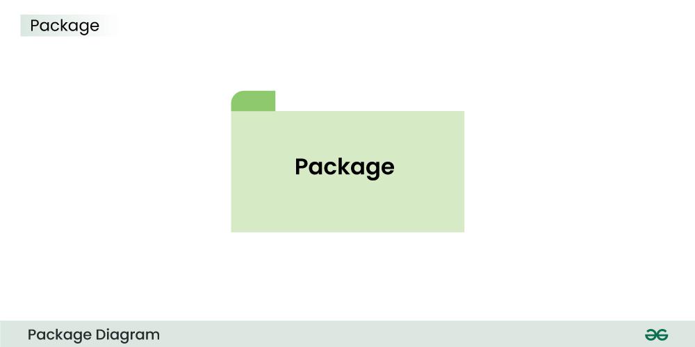
The above is the notation of a simple Package.
2. Subsystem

The above notation is used to represent subsystem.
3. Dependency
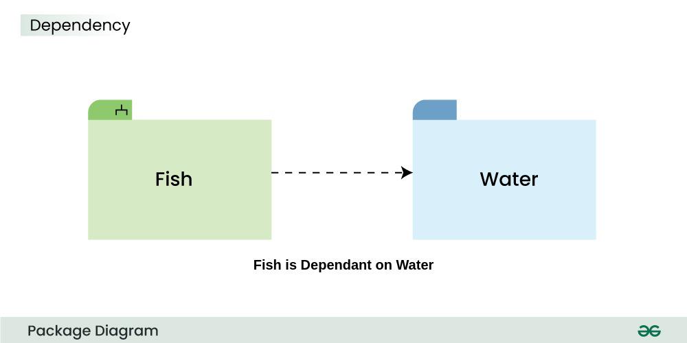
The above dashed arrow sign is used to show the dependency among two elements or two packages.
4. Import
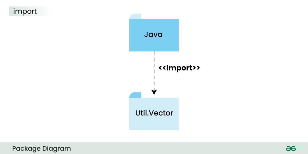
The above notation is of the Import, here it also uses a dashed arrow line but the difference is, the word <<import>> is being written to represent the below package or function or element has been imported from the above package.
5. Merge

This notation above denotes that the Package 1 can be merged with Package 2
Package Relationships
Package relationships define how packages interact, share information, and depend on one another within a system.
1. Package Merge Relationship
This relationship is used to represent that the contents of a package can be merged with the contents of another package. This implies that the source and the target package has some elements common in them, so that they can be merged together.
Example: In an e-commerce system, the Cash Payment, Online Payment, Card Payment, and Cheque Payment packages can be merged into a common Payment package. This combines shared payment-related functionalities while keeping individual payment methods organized separately.

The above diagram depicts that the packages are of different type of payments, but all of them are a some kind of payment mechanism, so they can all be merged to be called as payment.
2. Package Dependency Relationship
A package can be dependant on other different packages, signifying that the source package is somehow dependent on the target package.
Example: In an online shopping system, the Online Payment package depends on the Internet package to process transactions and communicate with payment gateways. If the internet service is unavailable, the online payment functionality may not work properly.

The above diagram depicts that the online payment package is dependent on the Internet package and uses "need" dependency.
3. Package Import Relationship
This relationship is used to represent that a package is importing another package to use. It signifies that the importing package can access the public contents of the imported package.
Example: In a geometry application, the Shapes package can be imported by packages such as Square, Rectangle, Circle, and Trapezoid to access common shape-related definitions and functionalities. This allows each package to reuse shared elements from the Shapes package without redefining them.

The above package diagram shows the import relationship between the main package Shapes and it's various other sub packages Square, Rectangle etc. They all are importing the real Shapes package so that the public contents of the Shapes package can be used by them.
4. Package Access Relationship
This type of relationship signifies that there is a access relationship between two or more packages, meaning that one package can access the contents of another package without importing it.
Example: In a web application, the Front End package can access services and data provided by the Back End package without importing all of its contents. This allows the front end to interact with backend functionality while keeping the packages loosely coupled.

The above diagram depicts the Access relationship between the Front End and Back End services. It is much needed that a front end service can easily access the important Back End services to carry out any operation.
Use Cases of Package Diagrams
Package diagrams help organize system elements into logical groups, making complex systems easier to understand and manage.
- Helps visualize the overall system structure by organizing related elements into manageable packages.
- Shows dependencies between packages, helping developers understand relationships and the impact of changes.
- Assists architects in breaking complex systems into smaller components for easier design and implementation.
Benefits of Package Diagrams
Package diagrams improve system organization, communication, and dependency management in software design.
- Provides a clear visual representation of the system architecture and package organization.
- Encourages a modular design approach by grouping related components into smaller packages.
- Helps developers and stakeholders communicate effectively while managing dependencies between packages.
Challenges of Package Diagrams
Creating package diagrams requires balancing clarity and detail while accurately representing system relationships.
- Maintaining the right level of detail can be difficult, as excessive information may reduce readability.
- Package diagrams mainly represent static structure and may not capture dynamic system behavior.
- Showing too many dependencies can make diagrams cluttered and harder to understand.
Tools and Software for Creating Package Diagrams
Some of the renowned tools and software used to create package diagrams are listed below -
- Enterprise Architect
- Lucidchart
- Visual Paradigm
- Draw.io
- IBM Rhapsody
- PlantUML
- StarUML
- Creately
- Microsoft Visio
